Country / Region
Country / Region
Copyright © 2018 New H3C Technologies Co., Ltd. All rights reserved. No part of this manual may be reproduced or transmitted in any form or by any means without prior written consent of New H3C Technologies Co., Ltd. The information in this document is subject to change without notice. |
|
Contents
A data center using the FC SAN technology usually contains separate LANs and SANs. LANs transport traditional Ethernet/IP services, and SANs transport network storage services.
To provide both IP services through LANs and storage services through SANs, data center servers use independent Ethernet adapters and FC adapters to access LANs and SANs, respectively. Such an implementation entails a large number of adapters, cables, and devices, and brings high maintenance costs.
Fibre Channel over Ethernet (FCoE) consolidates LANs and SANs to reduce the number of adapters, cables, and switching devices in the data center. This reduces costs.
Figure 1 FCoE for I/O consolidation
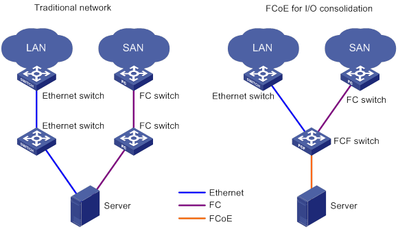
As shown in Figure 1, in the traditional network:
The server is connected to the LAN through an Ethernet interface.
The server is connected to the SAN through an FC interface.
In the FCoE network:
The server is connected to the FCF switch.
The FCF switch is connected to the LAN through an Ethernet interface and to the SAN through an FC interface.
The link between the server and the FCF switch can transmit both Ethernet frames and FC frames.
A switch that supports FC and FCoE is called an FCF.
An FCoE-capable node (server or storage) is called an ENode.
When an FC frame enters an Ethernet network, FCoE encapsulates it into an Ethernet frame for transmission. When the FC frame leaves the Ethernet network, FCoE decapsulates it from the Ethernet frame for further forwarding. This encapsulation/decapsulation process is called FC mapping (FCM).
In FCM encapsulation, an ENode is assigned a fabric-provided MAC address (FPMA).
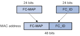
As shown in Figure 2, in an FPMA:
The 24 most significant bits is the FC-MAP.
The 24 least significant bits is the ENode's FC ID.
The FC-MAP is designed to generate FPMAs and is configurable. It is in the range of 0x0EFC00 to 0x0EFCFF and is 0x0EFC00 by default. The FC ID is assigned to the ENode when the ENode performs a fabric login.
In an FC network, two FC switches are connected through a point-to-point link. In an Ethernet network, two FCFs are connected through a multi-access link. Therefore, a virtual point-to-point link is required between FCFs in an FCoE network. It ensures that the FC protocol can run on the same topology as in a native FC network. A virtual FC (VFC) link is a point-to-point link that connects two VFC interfaces on two FCoE entities.
The FCoE Initialization Protocol (FIP) sets up and maintains VFC links.
The Data Center Bridging Exchange (DCBX) protocol exchanges the capabilities of DCE devices and configure parameters for peers.
In Ethernet, FCoE traffic and other traffic are differentiated by priority. Priority-based Flow Control (PFC) enforces flow control for FCoE traffic identified by its priority to ensure no loss of packets. Other traffic is not imposed with flow control.
Scheduling bandwidth in a round robin way (WRR), Enhanced Transmission Selection (ETS) ensures that the bandwidth on an Ethernet link is shared by FCoE traffic and other traffic.
FIP sets up VFC links between FCFs and ENodes. Then, FC can run on established VFC links.
FIP packets include the following types:
FIP Discovery Solicitation.
FIP Discovery Advertisement.
Virtual Link Instantiation Request.
Virtual Link Instantiation Reply.
FIP Keep Alive.
FIP Clear Virtual Links.
FIP VLAN Request.
FIP VLAN Notification.
Figure 3 shows a typical process for FIP to set up a virtual link between an ENode and an FCF.
Figure 3 Setting up a FIP virtual link
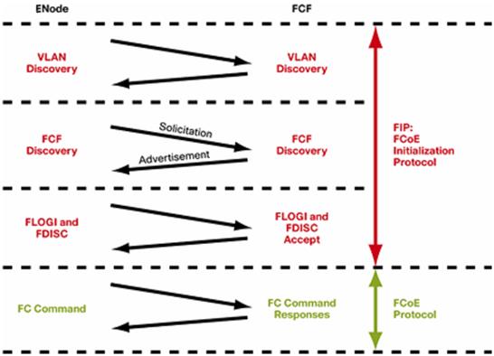
The ENode sends a FIP VLAN Request over an available VLAN (for example, port VLAN) to obtain the VLAN running FCoE (FCoE VLAN) from the FCF. The FIP VLAN Request sent must use ALL-FCF-MACs as the destination MAC address.
The FCF periodically sends unsolicited Discovery Advertisements to multicast MAC address All-ENode-MACs in all its FCoE VLANs. The following table shows the parameters carried in the Discovery Advertisement.
Parameter | Purpose |
FCF priority | Used for the ENode to choose an FCF for setting up a VFC link. |
Keepalive timer value | Used for the ENode to periodically send VFC link keepalive packets. |
FC-MAP | Used for the ENode to generate an FPMA. |
FCF MAC address | Used for the ENode to encapsulate and decapsulate frames in FCM. |
The ENode can send Discovery Solicitations to multicast MAC address All-FCF-MACs in the FCoE VLANs. In response to a Discovery Solicitation from the ENode, the FCF replies with a solicited Discovery Advertisement to the ENode.
The ENode sends a FIP FLOGI frame or FIP FDISC frame to the selected FCF to set up a VFC link. After receiving the FIP FLOGI frame or FIP FDISC frame, the FCF replies with a FIP ACC frame to allocate an FC ID to the ENode. Then, the ENode combines the FC ID and FC-MAP to generate an FPMA.
Two FCFs use FIP ELP frames to negotiate to set up a VFC link.
After the VFC link is set up, the ENode periodically sends keepalive frames, and the FCF still periodically sends unsolicited Discovery Advertisements. The FCF maintains the VFC link by monitoring the reception of keepalive frames from the connected ENode. The ENode or another FCF connected to the FCF maintains the VFC link by monitoring the reception of unsolicited Discovery Advertisements.
With a VFC link in place, the ENode and FCF can receive and send packets over VFC interfaces.
Figure 4 shows the FCoE frame format.
Figure 4 FCoE frame encapsulated in Ethernet
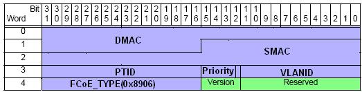
When the FCF sends a packet, it performs the following operations:
Encapsulates its FCF MAC address as the source MAC address.
Encapsulates the ENode FPMA or peer FCF MAC address as the destination MAC address.
When the ENode sends a packet, it encapsulates its FPMA as the source MAC address and the FCF MAC address as the destination MAC address.
The Priority field indicates the priority of the FCoE frame, defaulting to 3 and configurable.
The VLANID field identifies the VLAN that transports the FCoE frame.
Figure 5 FCoE frame forwarding
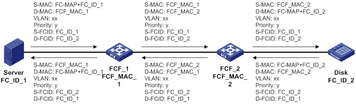
When forwarded through FCFs, an FCoE frame is decapsulated and encapsulated hop by hop. Figure 5 shows header information encapsulated at each hop.
The FCoE protocol makes sure the packets of one VSAN are transmitted in the same VLAN.
The MAC address of the ENode is a combination of the following:
The FC-MAP as the most significant 24 bits.
The FC ID of the ENode as the least significant 24 bits.
The FCF uses its FCF MAC address to send packets.
DCE ensures lossless transmission of FCoE frames over Ethernet by using PFC and ETS.
The FCF advertises its FCoE capabilities and the priority used by FCoE frames to the ENode through DCBX. The ENode encapsulates the FCoE frames with that priority.
The FCF reserves the amount of bandwidth (for example, the default 50%) specified by the user for that priority level. If the amount of other traffic is small, FCoE traffic can use more than 50% of the total bandwidth. In the event of large amounts of other traffic, FCoE traffic is guaranteed 50% of the total bandwidth.
When the bandwidth is insufficient for FCoE traffic, the FCF sends a pause frame to notify the upstream device to stop transmitting FCoE frames. When congestion disappears, the FCF notifies the downstream device to continue transmitting.
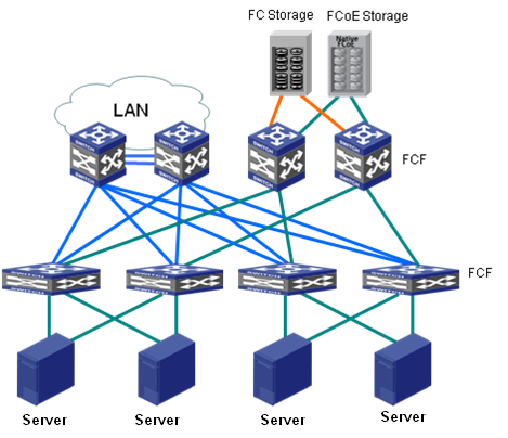
As shown in Figure 6, the server connects to the FCF through a converged network adapter (CNA). The FCF connects to the LAN and SAN through Ethernet switches and FCFs, respectively. Both FCoE and FC storage devices are supported in the SAN.
Figure 6 FCoE application scenario